Introduction
Mazdas i-stop system stops the engine when the car is not moving. It’s a clever and well engineered “hack” to get better results on the emission tests.
When the system decides to stop the engine, the pistons are stopped at a very specific position. This makes it possible to restart a gasoline engine without using the starter motor.
For a diesel engine, the starter motor is used, and Mazdas official explanation is a bit “fuzzy”:
Unlike gasoline engines, which use a spark plug to ignite the air-fuel mixture, diesel engines compress the mixture until it spontaneously combusts. Therefore, to restart a diesel engine, sufficient compression is required.
While conventional diesel engine idling stop systems require two engine cycles to restart, Mazda’s unique i-stop needs just one cycle, thanks to its precise control of the piston positions.
According to Mazda, the gasoline engine is restarted in 0.35 seconds, the diesel engine in 0.40 seconds. Mazda calls these measurements “internal measurement on vehicles with automatic transmission”, meaning that they should be taken with a grain of salt.
The real numbers are higher, especially for diesel engines.
The i-stop system is enabled by default. It has to be deactivated on every trip.
This project shows you how to use a micro controller to create an “i-stop disabler” or “anti i-stop” device that turns the i-stop system off when the engine is started.
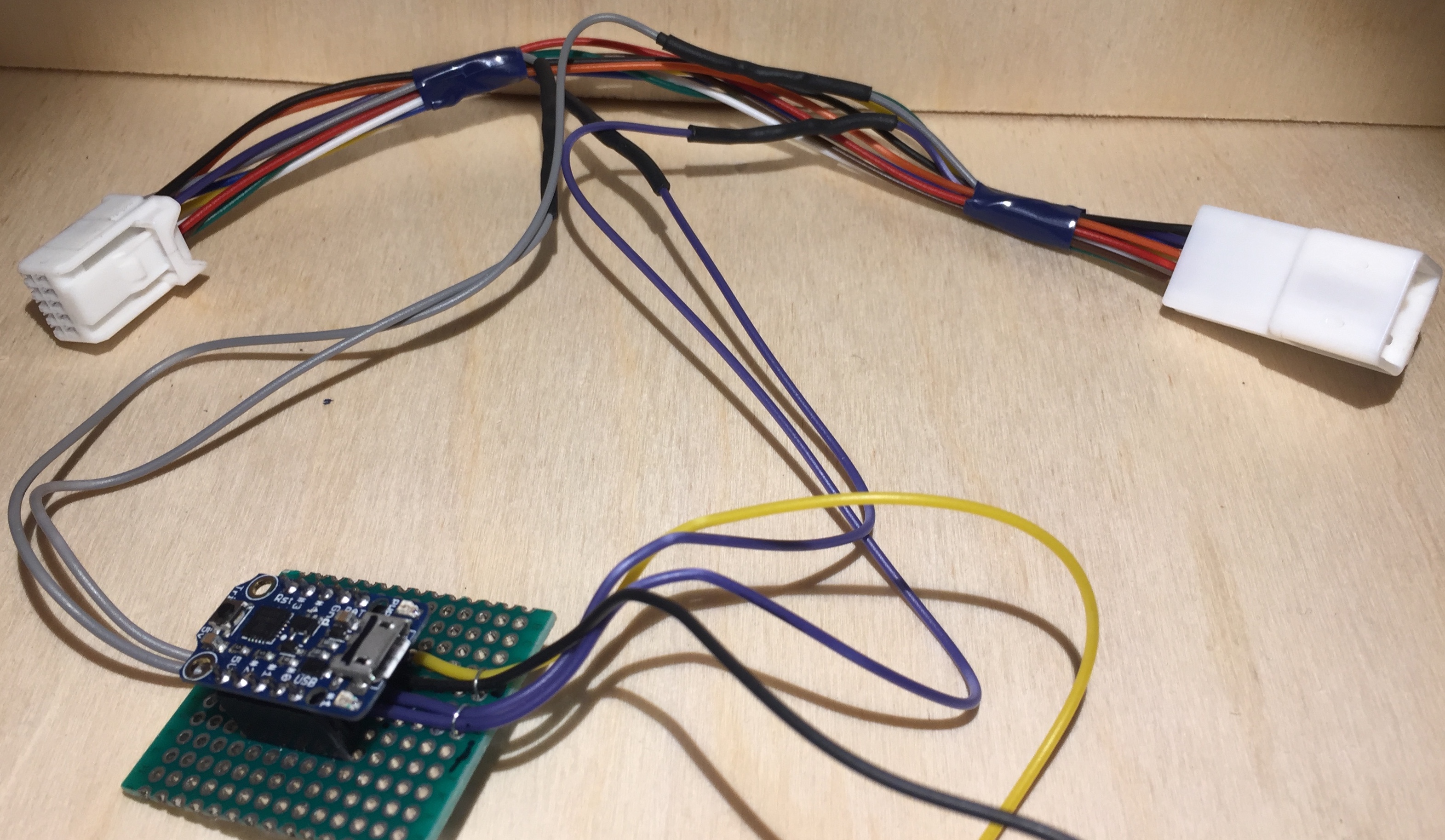
Table of contents
- Introduction
Other ways to disable the i-stop system
There is a number of creative suggestions around the web for disabling the i-stop system. Some are quite crude, and others have side effects.
Using brake pedal pressure
Learn to control the i-stop activation by applying the correct brake pressure.
If you press hard on the brake pedal, the i-stop system activates. Light pressure keeps the engine running.
The “after engine start” checklist hack
Just like airline pilots have checklists for everything, make your own routine of always remembering to disable the i-stop system manually.
The hood switch hack
There is a switch in the engine compartment used to detect if the hood is open or closed. Disabling this switch “tricks” the car into thinking the hood is open, disabling the i-stop system.
This hack makes it impossible to activate the i-stop system without opening the hood and enabling the switch.
Note! Disabling this switch could interfere with the cars alarm system.
The paper hack
Wedge a piece of paper into the i-stop button, pressing it in permanently.
This approach works, but has one big drawback. Three of the buttons in the cluster switch stops working.
The OBDII hack
Write some magic values to the cars computer using the OBDII port. This might work if you know what you’re doing, but seems risky.
Micro controller based solution
Using a micro controller to simulate pressing the i-stop button seems like the best option.
The goals for the project are:
- Easy to build/assemble
- Easy to install
- As simple as possible
- Non invasive installation. The modification can be removed without leaving any traces. Which means that splicing into the cars wire harness, is a big no-no.
- Possible to quickly disable it. Useful when delivering the car to the dealer for service.
Similar projects
A German guy has already made a micro controller solution, which I didn’t like for several reasons:
- A hardware programmer is required to upload the software to the micro controller
- Requires modification to work with the Mazda i-stop system
- Source code for the micro controller is not available
How the cluster switch works
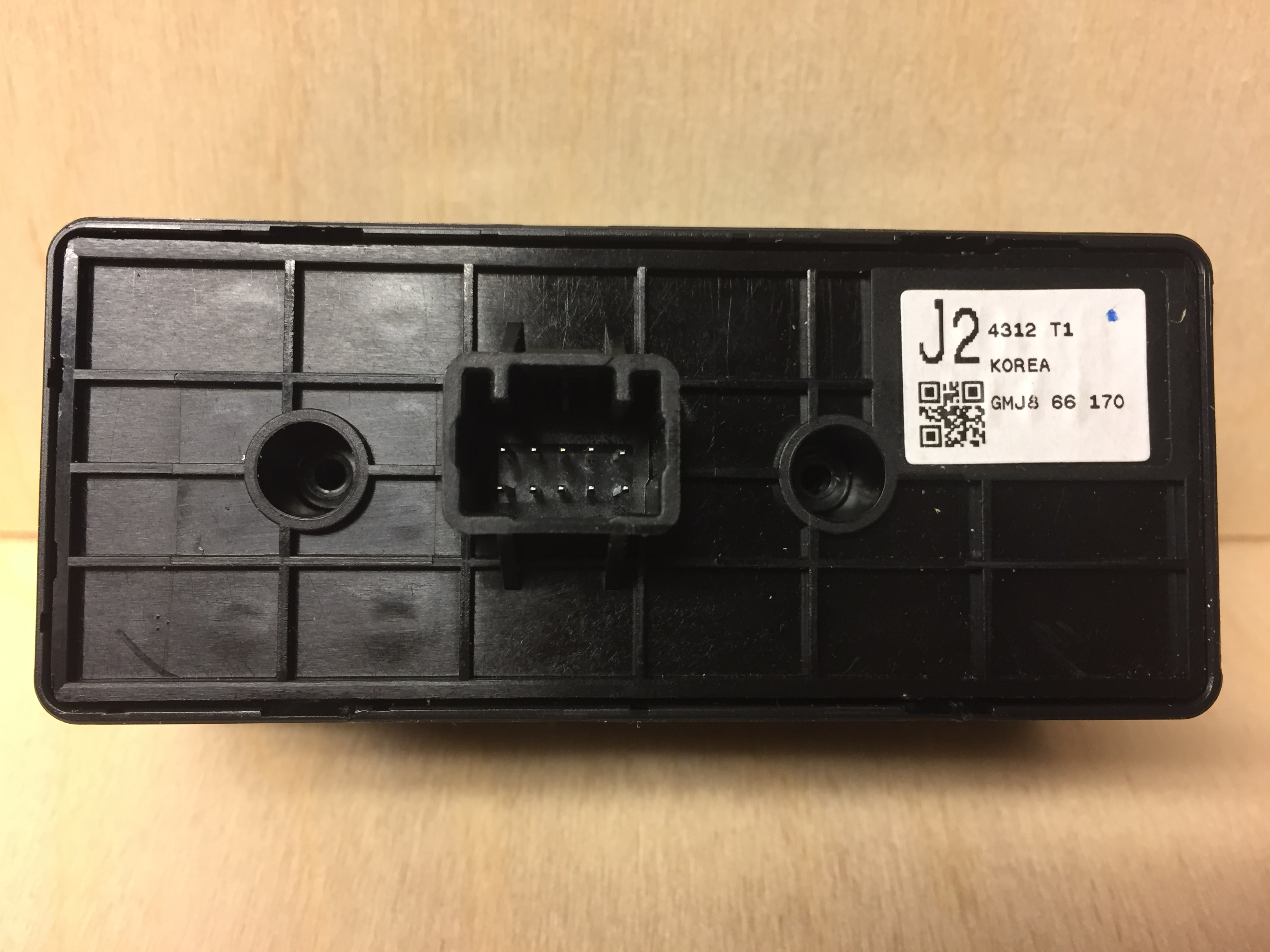
The cluster switch (part number GMJ8-66-170) has five buttons in the front, and a 10 pin connector at the back.
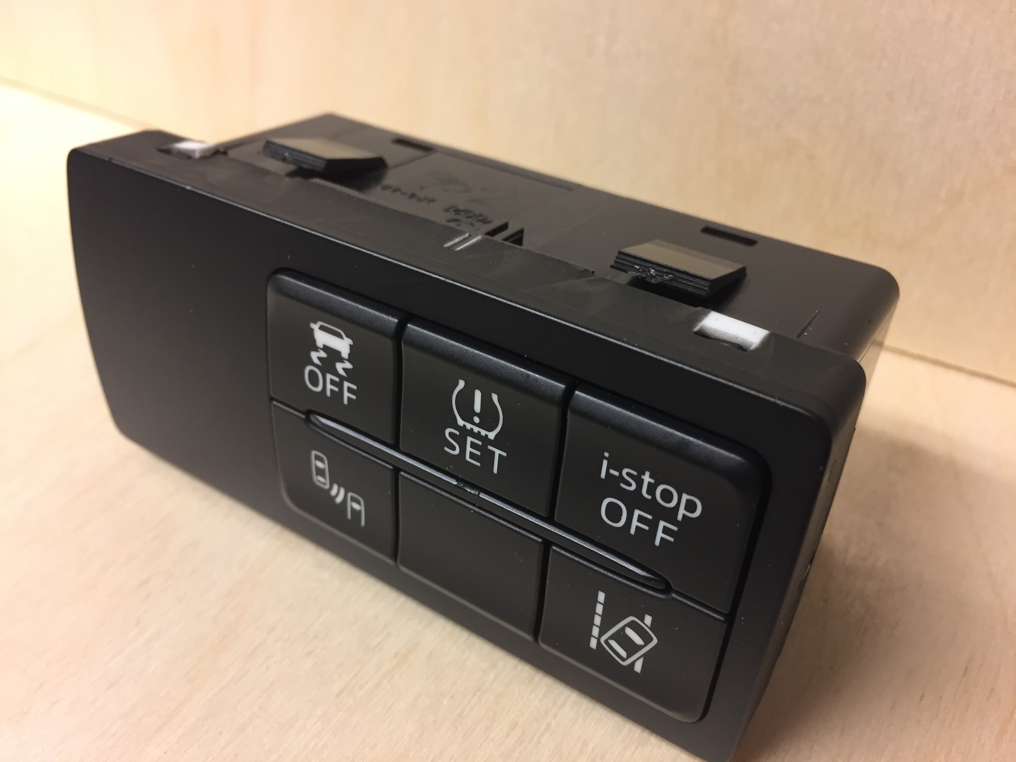
Two of the ten pins are used to detect which of the five buttons that are pressed.
This observation is confirmed by looking at the Mazda repair manual.
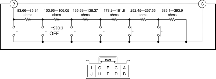
Since the buttons are arranged in series with six resistors, it’s not possible to detect if two buttons are pressed simultaneously, which is the drawback of the paper hack.
When the i-stop button is pressed, the resistance between terminals C and B should be 83.66-85.34 ohm.
Measuring the circuit with a multimeter confirms the information in the repair manual.
| Pin | Usage |
|---|---|
I |
Ground for the leds/back light |
G |
Unused |
E |
Unknown |
C |
Button resistors |
A |
Unused |
J |
+12v for the leds/back light |
H |
Unused |
F |
Unknown |
D |
Unknown |
B |
Button resistors |
Inside the cluster switch is a circuit board labeled ALPS AJM971172A.


How the micro controller works
A micro controller is just a cheap, simplified and slow computer. A small program is uploaded to the micro controller. When the micro controller is powered on, it just starts running the program that was uploaded to it.
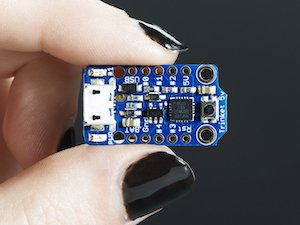
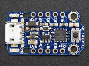
The micro controller (attiny85) is on a small board called “trinket”. The trinket board has a voltage regulator (5.5-16V) and USB plug for uploading code. More technical details about the trinket can be found here.
The micro controller is powered from the ignition (IGN in the schematic), through a fuse tap from the cigarette socket fuse.
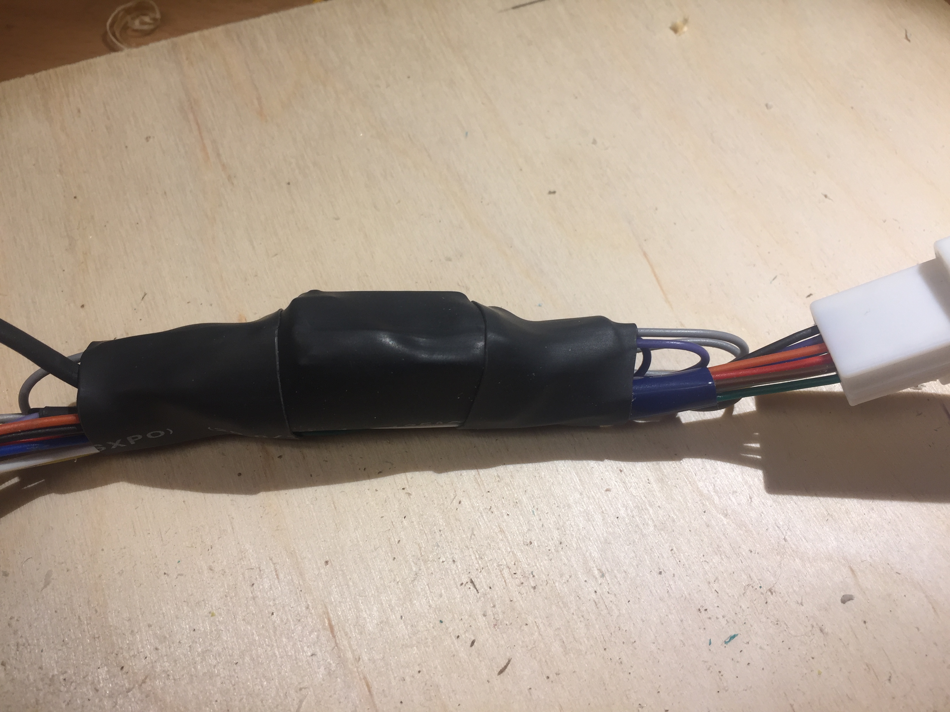
It “hooks” into the cluster switch through a pair of 10 pin OEM connectors, and sits between the cluster switch box and the wiring harness.
When the engine starts, the micro controller activates a small relay simulating an i-stop button press. After the button press has been simulated, the micro controller goes to sleep. When the engine is stopped, the micro controller is powered off, and the cycle repeats the next time the car is started.
How to build
This is a simple and fun project to build, provided you have the necessary tools, some basic electronics skills and a little experience with Arduino compatible micro controllers.
Schematic
The circuit consists of only four components:
- Trinket board (micro controller)
- 1N4007 diode
- 85 ohm resistor
- DPDT relay
Important notes!
-
The DPDT relay is a tiny signal relay specially selected for this application. If you want to use a different relay than the one specified in the BOM, take a look at the FAQ first.
-
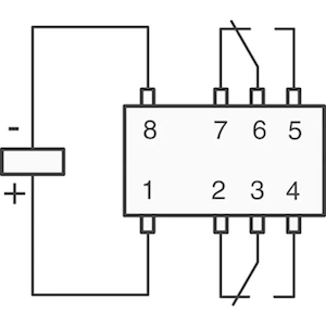
In the schematic below,
PIN3on the trinket is used to activate the relay.GNDandPIN3lines up with the relay terminals8and1, eliminating the need for jumper wires.
SincePIN3is shared with the USB connector, Adafruit recommends disconnecting this pin before uploading new code to the micro controller.
The easiest workaround for this is to use headers for connecting the trinket to the rest of the circuit.
ECU TERMINAL#C -----------------------------+
                                            |
CLUSTER SWITCH TERMINAL#C -------------- +  |
                                         |  |
    +-------------------------------+    |  |
    |  IGN                          |    |  |
    |   |             +=========+   |    |  |
    |   +------- BAT--‖         ‖   |    |  |
    |----------- GND--‖ TRINKET ‖   |    |  |
    |                 ‖   5V    ‖   |    |  |
GND-+       +--- PIN3-‖         ‖   |    |  |
            |         ‖         ‖   |    |  |
            |         +=========+   |    |  |
            |                       |    |  |
            |               +-------+    |  |  +--------+
            |               |       |    |  |  |        |
            |               |    +================+     |
            |             +---+  ‖  8    7  6  5  ‖   +---+
            |             | | |  ‖        |\   |  ‖   | Z |
            |      1N4007 | V |  ‖  RELAY DPDT    ‖   | Z | 85 OHM
            |      DIODE  | ‾ |  ‖        |/   |  ‖   | Z | RESISTOR
            |             | | |  ‖  1    2  3  4  ‖   | Z |
            |             +---+  +================+   +---+
            |               |       |    |  |  |        |
            |               +-------+    |  |  +--------+
            |                       |    |  |
            +-----------------------+    |  |
                                         |  |
CLUSTER SWITCH TERMINAL#B ---------------+  |
                                            |
ECU TERMINAL#B -----------------------------+
If the micro controller is not powered, the i-stop button works as if the modification was not installed. When the relay is not energized, the relay pins 2+3 and 7+6 are connected.
So to temporarily disable this modification, just remove the power to the micro controller (IGN in the schematic).
While the relay is energized, none of the buttons in the cluster switch will work.
Bill of materials (BOM)
A list of all the parts needed to complete the build.
| Amount | Description |
|---|---|
| 1 | Adafruit trinket 5V |
| 1 | Piece of perfboard |
| 1 | DPDT signal relay |
| 1 | 1N4007 diode |
| 1 | 85 ohm resistor |
| 2x4 | Male headers |
| 2x4 | Female headers |
| 10 x 30 cm | 0.35 mm wire, ideally 10 different colors |
| 1 | Sumitomo 10 pin male housing 6098-3869 |
| 1 | Sumitomo 10 pin female housing 6098-3909 |
| 10 | Sumitomo male terminals 8100-3624 |
| 10 | Sumitomo female terminals 8100-3622 |
| 4 | Zip ties |
| 1 | Fuse tap |
| 1 | 1A blade fuse |
| 1 | Heat shrink tubing |
Notes:
- The adafruit trinket was chosen for convenience, since it’s programmable via USB and has an on-board voltage regulator (5.5-16V).
- The DPDT relay draws only 10 mA of current, so using a transistor for powering it is not necessary.
- The relay pins does not line up perfectly with a perfboard, but the feet are small and flexible, so they can be adjusted.
- 85 ohm is not a very common resistor value. If you don’t have that value, use two or more resistors in parallel.
Two resistors with the values 91 ohm and 1200 ohm will result in ~84.6 ohm resistance. Use a parallel resistance calculator to find the right combination. Verify the result with a multimeter.
Source code
The code running on the micro controller is quite simple.
When the micro controller is powered on, it activates the relay for 2.5 seconds to simulate pressing the i-stop button, and then goes to sleep.
#include <avr/sleep.h>

const int RELAY_PIN=3;

void setup() {
  pinMode(RELAY_PIN, OUTPUT);
}

void loop() {
    digitalWrite(RELAY_PIN, HIGH);
    delay(2500);
    digitalWrite(RELAY_PIN, LOW);

    while(true){
        set_sleep_mode(SLEEP_MODE_PWR_DOWN);
        sleep_enable();
        sleep_cpu();

        delay(4294967295L);
    }
}
Take a look at Adafruits guide on how to upload the code to the trinket board.
Assembly
Some tips:
- Get a sharpie and put a black mark on the negative terminal (
8) of the relay. - Assemble the female connector first, as it’s more difficult to assemble than the male connector.
- Use a good crimping tool for the connector terminals. If the terminals are bent and distorted by the crimping tool, it will be really hard to slide the terminals into the connector housing.
- Use wires with 10 different colors to reduce the risk of incorrect wiring.
- Remember to disconnect the trinket from the circuit before programming it via USB, otherwise you’ll have to repair the trinket bootloader, which requires a separate Arduino board.
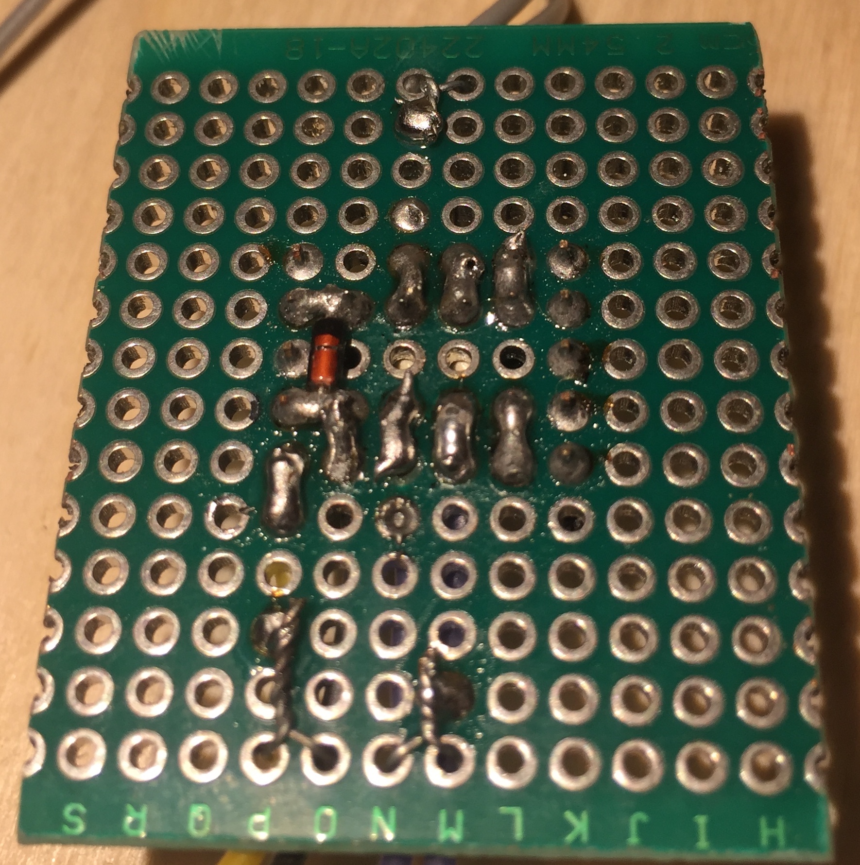
The pictures below shows just one of many ways to build this project.
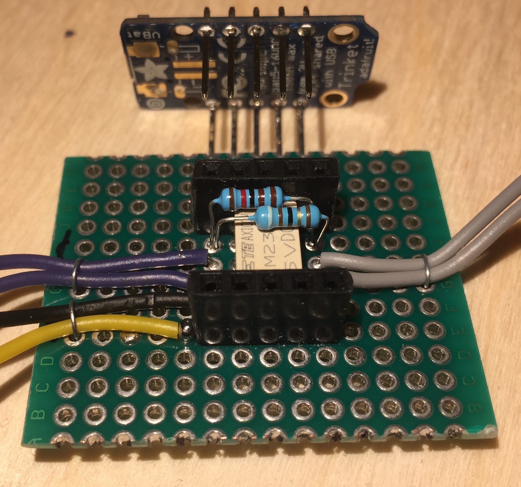
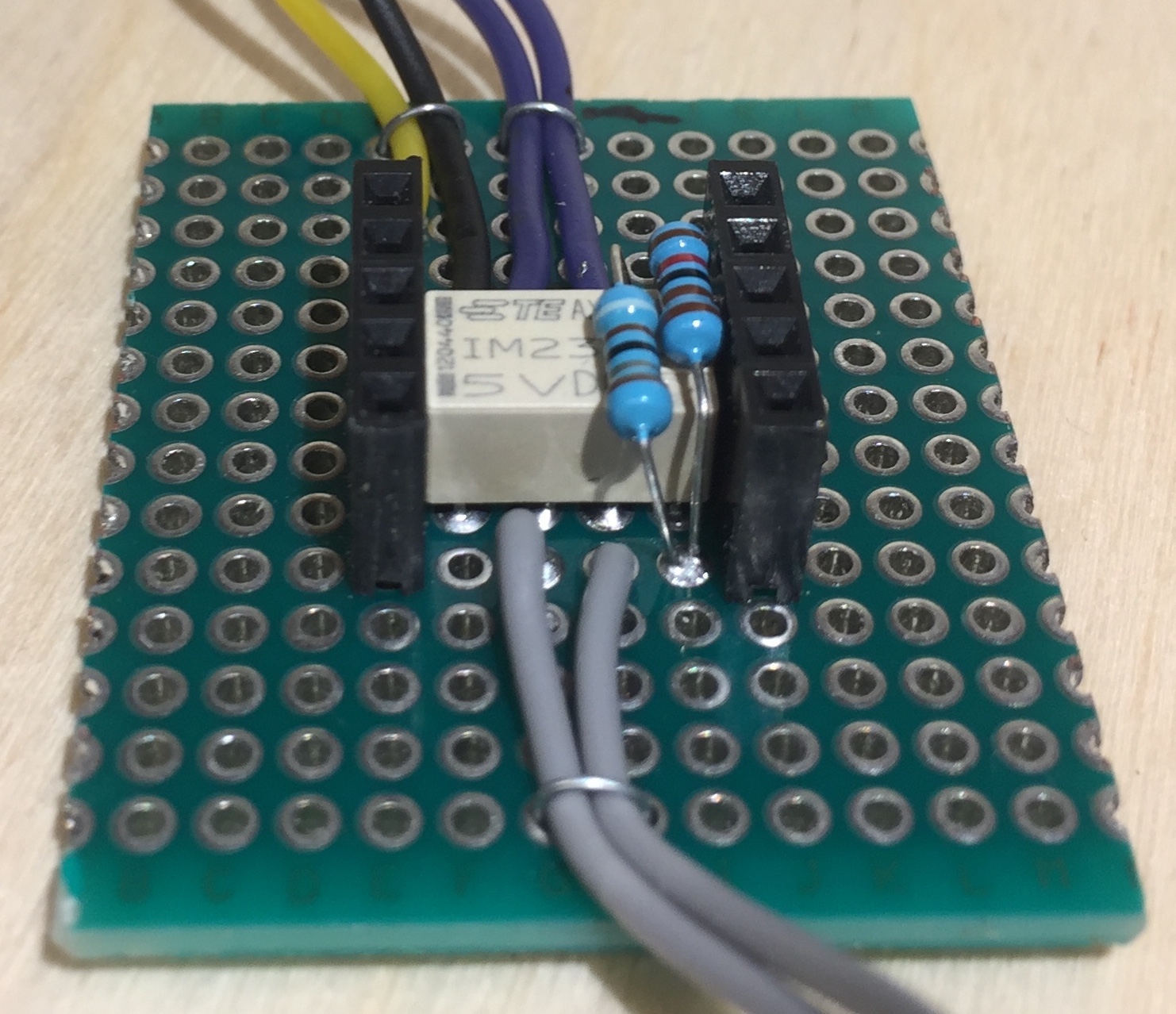
The trinket is attached to the perfboard via header pins, allowing easy removal when programming it via USB.
Yellow wire is IGN, black is GND.
Verification/testing
It’s a good idea to verify that everything is wired correctly before installation.
- Use the continuity function of the multimeter to test all the pins of the connectors.
- Ensure that no wires are swapped in the connectors. Using wires with 10 different colors makes this easier to verify.
- Connect the multimeter to pin
Cof the male connector, and pinBon the female connector. When the trinket is powered on, the resistance should be around 85 ohm.
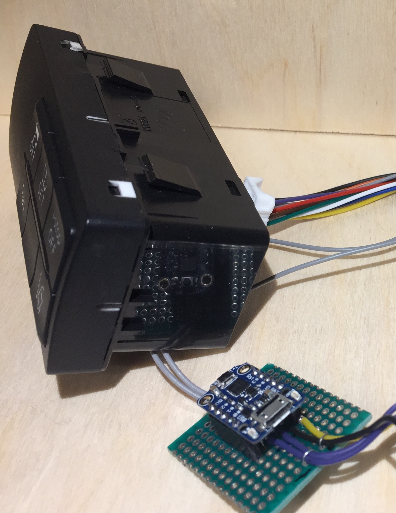
Installation
DISCLAIMER:
This modification is installed at your own risk! It works in my European 2015 Mazda 6, but I can’t give you any guarantee that it will work on your Mazda. Use the information provided here to figure out how the modification works, and then decide if you want to add it to your vehicle.
Follow the repair manual instructions on how to remove the cluster switch.
An alternative approach is to remove the coin tray below the cluster switch. This apporach works, but it’s very fiddly to remove the cover behind the coin tray. It’s quicker to just follow the repair manual instructions.
It’s also a good idea to invest in a set of plastic panel removal tools before starting the installation.

FAQ
Where do I buy the Sumitomo 10 pin OEM connectors?
The 10 pin Sumitomo connectors are difficult to source. Finding a supplier is not easy, and most are not willing to sell in small quantities.
I sell the connectors for $25, including shipping. I get $5 in profit per connector, which should cover the time I spend packing and shipping, and the expenses I’ve had researching this project (~$400).
All sold out, sorry..
Buying automotive OEM connectors in small quantities is expensive. And import taxes and shipping adds to the cost.
Finding the correct connectors took a lot of time and some money, so I have done you a huge favor by supplying the part numbers in the BOM. So you have the option of buying them somewhere else.
Known limitations?
Won’t work if just the ignition is turned on, and the engine is started later. As soon as the micro controller is powered on, it assumes that the engine has been started.
It’s possible to detect if the engine is actually running, but I have not found a way to do this without adding a significant amount of complexity.
Which Mazda models does this modification work on?
So far it’s been installed in an European 2015 Mazda 6 2.2 AWD.
Send me an email (address at the bottom) if you have successfully installed this in your vehicle.
Can I use a different relay?
Yes, but the trinket can only deliver 20 mA of current on a pin. The relay in the BOM draws only 10 mA, is really small, quiet and makes the whole assembly compact.
Most relays draws more than than 20 mA, so you need a transistor to switch it on. The transistor must also have resistor in front of it. And you might need a different flyback diode.
This adds two extra parts to the build, and complicates the wiring and soldering.
Will the relay wear out?
A relay has moving parts. When it’s energized, a magnet moves a pair of contacts which makes an audible click. Eventually, the relay will wear out.
According to the relay data sheet, it’s good for 10⁸ operations, or 100 million operations.
If you start your car 100 times every day, the relay will wear out after ~270 years. In other words, it will outlive your car.
Will it void my warranty?
This modification can be removed without leaving any traces, it would be hard for the dealer to prove that you have done anything wrong.
How much does it cost to build?
Provided you already have the necessary tools, somewhere between $30 and $90, depending on where you source the parts.
It’s possible to build this using cheaper/other parts, but I’m not an electronics expert. I just wanted something that was quick and easy to put together.
Questions, comments or suggestions?
If you have any questions, comments or suggestions, please drop me an email at:
Please note that I don’t have the time to “hold your hand” and walk you through this project step by step.